Tracing
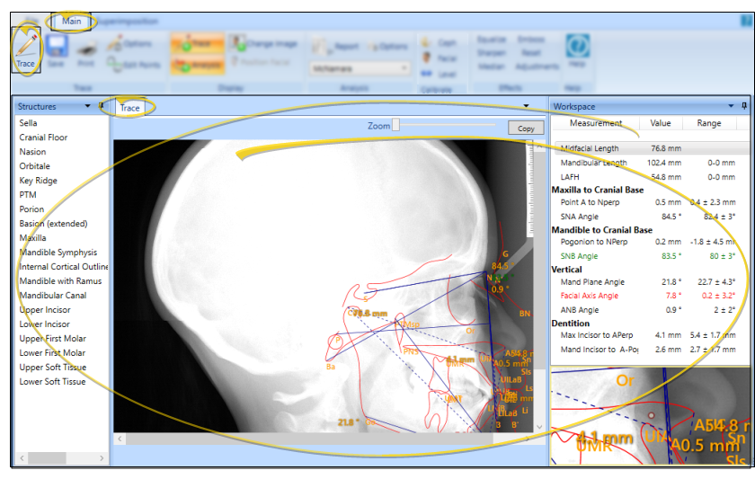
While tracing a patient's lateral ceph, SmartCeph calibrates the image, and guides you through all the structures and landmarks needed to fully digitize the ceph to comply with your selected analysis. You can position and rotate structures, place specific points, use ribbon bar tools, right-click rotation, and keyboard shortcuts to make the tracing as accurate as possible.
Enable Tracing Mode
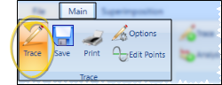
Select the  Trace icon from the Trace section of the SmartCeph Main ribbon bar. When Trace mode is enabled, the Trace icon in your Main ribbon bar will have a gold background.
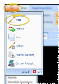
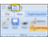
Alternately, you can select the Trace option from the File ribbon bar.
Continue or Remove Existing Points- If the ceph you are viewing already has a tracing, you are asked whether you want to remove all plotted points and start over, or continue the trace where you left off. If you have just recalibrated, we recommend starting over. Otherwise, choose your answer depending on your needs for that ceph.
Tracing the Ceph
-
Calibrate the Ceph - If your ceph was not created using a digital pan ceph unit, SmartCeph prompts you for two points of measurement. Position your pointer on the metric ruler you have included on your ceph and click. Then move your pointer the distance you have set for measurement and click again. See "Calibration" for details.
noteTo be the most precise when calibrating the ceph, be sure to use to use the zoom window in the bottom right corner of the screen.
-
Confirm Analysis Selection
- Before you begin tracing, confirm the analysis you want to use is selected in the Analysis section of the Main ribbon bar, to assure that you will be tracing all necessary structures. (If you have custom analysis files that are not listed, be sure the Path to Custom Analysis field of your Analysis Options is correct. See "Analysis Options" for details.)
noteTo be able to use the full set of ABO-required structures for the ABO Case Submission integration in Edge Imaging, you must select the ABO Analysis as your analysis.
-
Plot the Landmarks and Structures
- When you begin a new tracing, SmartCeph automatically places the first structure for you to position on the ceph, with your cursor as close as possible to the appropriate landmark point. Once you set that structure, SmartCeph automatically moves on to the next structure in the list. Be sure to use SmartCeph tools, described below, to plot the landmarks and structure as accurately as possible.
Position the Structure - Move your mouse over the ceph image to position the selected structure. When the structure is in place, click your left mouse button to "set" it.
Rotate the Structure - Right-click and drag to rotate the selected structure. When you release the right mouse button, you can continue dragging the structure into position. When ready, click your left mouse button to "set" the structure in place.
Multi-Point Structures - Some landmarks and structures will require multiple points or rotations. SmartCeph will prompt you for each position as necessary. For example, when you plot the incisors, you first click to plot the tip, then when you move your mouse, the structure rotates so you can plot the root.
tipWhen placing a structure with multiple points, if you have a hump, hold down the right click, drag up, and then release and move your mouse back to its original position. If you have a valley, hold down the right click, drag down, release, and move your mouse back to its original position. Doing this correctly the first time will be faster than editing the individual points later.
Edit Individual Points - To fine-tune individual points while tracing a ceph, hold down the Ctrl key on the left side of your keyboard. Then click and drag individual points as needed to make your tracing as accurate as possible. When you release the Ctrl key, you can continue tracing where you left off. While viewing a completed ceph tracing, you can click the Edit Points icon on the Trace section of the Main ribbon bar, then click and drag individual points as needed. See "Edit Points" for details.
-
Continue Plotting
- Once you "set" a structure in place, SmartCeph goes on to the next structure or landmark in your Structures list. If you want to place a different structure, or if you want to re-plot a structure you have already placed, simply click that structure name in the list. When you have "set" that structure, SmartCeph will continue prompting for the next structure in the list.
noteOnly the points required for the selected analysis are placed during the guided tracing. Additional points can be edited with the Edit Points feature See "Edit Points" for details.
-
Calibrate With Photo - If the Upper Soft Tissue structure is included on your structure list, and the patient has a lateral facial photo, after all the points have been placed the patient's lateral photo will appear and you will be prompted to identify the Pronasale and Labial Sulcus. This enables SmartCeph to align the photo with the trace. If you import the lateral facial photo later, you can use the Calibrate tool to align the ceph with the photo. See "Calibration" for details.
-
Save Changes
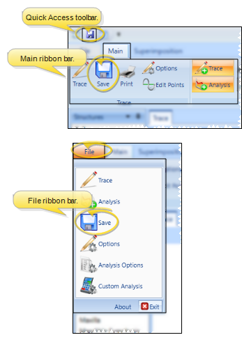
- Click Save in your Quick Access toolbar, Main ribbon bar, or File ribbon bar (or press Ctrl+S on your keyboard) to save any changes you have made.
Whenever you save a traced ceph in SmartCeph, a copy of the traced ceph, traced facial lateral photo, and trace wigglegram are automatically saved in the appropriate timepoint of the patient's Edge Imaging page, overwriting any existing files in that same timepoint. You can view these images from the Index layout, or from any layout that includes the Traced Lateral Ceph, Traced Photo, or Traced Lateral image types.
Trace Window Tools and Tips
Window Display Options
- By default, only the tracing you are working on shows on your ceph as you plot the structures. However, you can use the icons in the Display section of the Main ribbon bar to enable / disable additional overlays as needed, as well as manually position the facial photo.
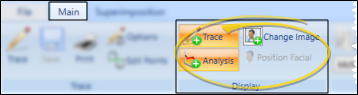
Trace - Enable / disable this tool to show / hide the ceph tracing. Your trace options determine whether you see landmark abbreviations when the trace is displayed. See "Trace Options" for details.
Analysis - Enable / disable this tool to show / hide the analysis from the display. If you attempt to display an analysis for which you have not placed all the necessary points, a message will inform you. See "Analysis Review" for details.
Change Image - Click this tool to progress through the background image type: ceph , photo, or none.
Position Facial - When the facial photo is displayed on the Trace window, you can click this option, then use your arrow keys to manually place the photo wherever needed to best line up with the tracing. This option is available only after the facial photo has been calibrated to the ceph. See "Calibration" for details.
Current Landmark Reference - While tracing, the upper portion of the Workspace area shows you the graphical representation and technical terminology for the currently selected landmark.
Abbreviation / Audio Prompt - You may or may not see landmark abbreviations on your ceph, or hear audio prompts during tracing, depending on your SmartCeph settings. See "Trace Options" for details.
Visual Tools - Use the controls on the Effects section of the Main ribbon bar to visually enhance the ceph and help make finding points easier. See "Visually Enhance a Ceph" for details.
Zoom Window - You may or may not see the structure markings in the Zoom Window at the bottom portion of the Workspace area, depending on your SmartCeph settings. We recommend you use the Zoom Window to achieve the most precise tracing.
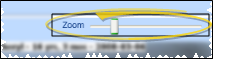
Zoom Slider
- You can click and drag the zoom slider at the top of the work area to make the image bigger or smaller. If you make the image larger than the window, scroll bars will appear at the bottom and / or right edges of the window so you can move the focus to see the entire image.
Toggle Full Screen Mode
- Select the Full Screen Toggle icon from the Quick Access toolbar at the top of the SmartCeph window to maximize / minimize the SmartCeph work area. When full screen mode is enabled, SmartCeph minimizes the ribbon bar and pins the workspace and structures areas so that your main work area space is as large as possible, maximizing the visual presentation of your SmartCeph analysis.
Copy or Print the Image - Use the Copy button at the top of the work area, or the Print icons on the ribbon bar to make a copy or a print-out of the current image. The result will include an actual-size picture of the current image, including any overlays. For example, if you have displayed the tracing, analysis, and facial photo, the resulting picture will include all these items. But if you disable all other features so you are only looking at the ceph, your picture will include only the ceph image.